
 English
 عربى
 中文简体
 русский
 Français
 Deutsch
Why Reinforced Introducer Sheath Design Matters in Multi-Level Intravenous Cannulation
Designing components for multi-level intravenous cannulation is a demanding task for device engineers. A tubing path that must carry several channels, guide wires and auxiliary instruments can fail in predictable ways. The wall may kink at a tight radius, the lumen may collapse under axial load, or the push force may climb until the assembly becomes difficult to control. Many of these problems cannot be solved by polymer choice alone. They depend on how the tubing wall is built and how the sheath behaves under repeated handling.
This article looks at the tubing side of the problem. It focuses on the reinforced sheath, which forms the structural backbone of a multi-level intravenous cannulation assembly. We explain the material and structural logic behind a wire reinforced introducer sheath, the performance criteria that engineers and purchasing teams should check, the common integration scenarios, and the custom manufacturing options that OEM projects typically require.
All content is written from the perspective of a medical catheter component supplier. We provide semi-finished tubing that downstream manufacturers integrate into their own finished devices, so the discussion stays focused on component design, dimensions, materials and manufacturing practice.
Understanding the Component Requirements of Multi-Level Cannulation
What multi-level cannulation demands from a device designer
From a device development standpoint, a multi-level access design needs a support structure that can hold its shape while several elements pass through it. The sheath must maintain a consistent inner diameter along its full working length, transmit push force without buckling, and recover its geometry after being bent. Designers also need the tubing to accept repeated insertion and withdrawal of instruments without surface damage or lumen distortion.
Because these requirements interact, a change in one property usually affects the others. Increasing wall stiffness improves radial support but reduces flexibility. Lowering friction helps instrument passage but can make a sheath harder to bond or join. Good component selection means balancing these trade-offs against the specific geometry and use conditions of the finished device.
Core performance criteria for introducer sheath tubing
Engineering and purchasing teams usually evaluate reinforced sheath tubing against a common set of criteria. The table below summarizes the most frequently requested properties and why each one matters at the component level.
| Criterion | What it describes | Why it matters |
|---|---|---|
| Kink resistance | Ability to bend without collapse | Keeps the lumen open during routing |
| Radial support | Resistance to wall deformation | Protects the working channel |
| Controlled flexibility | Bending stiffness along length | Matches the target path geometry |
| Low surface friction | Ease of instrument passage | Reduces push force variation |
| Chemical resistance | Stability with contrast media and solvents | Supports finished device compatibility |
| Sterilization tolerance | Dimensional stability after sterilization | Preserves geometry across processing |
A reinforced vascular access catheter tubing that meets these criteria consistently is easier to integrate, validate and scale. Suppliers who can document test results against each criterion help their customers reduce development time.
Structure of a Wire Reinforced Introducer Sheath
FEP as the base material for vascular sheath tubing
Fluorinated ethylene propylene, commonly called FEP, is widely used as the polymer layer in reinforced sheath tubing. It offers low surface friction, good optical clarity, resistance to many chemicals and solvents, and compatibility with common sterilization methods. These properties make FEP a practical base for a FEP vascular access sheath where smooth instrument passage and dependable wall behavior are required.
FEP also processes well into thin walls. Engineers can tune wall thickness within a narrow range to balance lumen size against overall outer diameter. This matters in multi-level designs, where every fraction of a millimeter affects how many elements can share a limited cross section.
Spring coil reinforcement for interventional sheath design
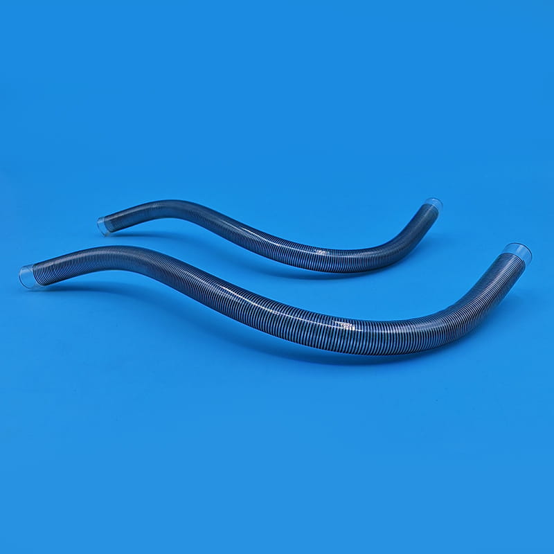
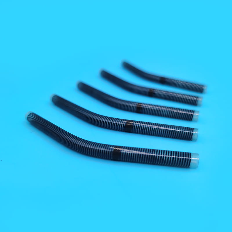
A spring reinforced FEP sheath places a helical metal wire between two polymer layers. The coil carries hoop load, so the wall resists flattening when the tubing is bent or pushed. The polymer layers, in turn, keep the lumen smooth and seal the coil from the working environment. The result is a sheath that stays flexible along its length while maintaining an open channel.
Coil geometry controls much of the performance. Wire diameter, pitch and the number of coil turns per unit length each influence stiffness and kink resistance. A tighter pitch generally increases radial support and reduces the bend radius at which the wall begins to deform, while a wider pitch increases flexibility. Component designers select these parameters according to the target path and the instruments that must pass through the sheath.
The figure below shows the layered wall structure used in a typical wire reinforced introducer sheath.
Design Benefits of Spring Reinforced FEP Sheath
The reinforced structure delivers several practical benefits for component suppliers and the device teams that integrate their tubing. These benefits are most visible when a sheath must perform reliably across many insertions and in tight routing paths.
Kink resistance
The coil keeps the lumen open during bending, which lowers the chance of wall collapse during device deployment.
Balanced stiffness
Radial support and flexibility can be tuned together through coil pitch and polymer wall thickness.
Smooth lumen
The FEP inner liner provides low friction, supporting consistent passage of auxiliary instruments.
Process compatibility
FEP tolerates common sterilization routes and chemical exposures found in finished device workflows.
- Lower component failure risk during device assembly and handling.
- More repeatable push force when instruments are exchanged through the sheath.
- Better dimensional stability across the processing and sterilization steps.
- Greater design freedom for customers who need a custom length or diameter.
For a component supplier, the central value of a reinforced structure is predictability. A sheath that behaves the same way across production lots lets the downstream manufacturer focus on finished device validation rather than tubing variation.
Common Applications for Reinforced Introducer Sheath Components
Component for central venous access device development
Central venous access devices often require a sheath that can hold a defined channel while the finished product is routed through a longer and sometimes curved path. A reinforced design with controlled stiffness gives the device developer a stable tubing platform that can be adapted to different catheter lengths and tip configurations.
Percutaneous interventional access sheath tubing
In interventional device families, a vascular sheath must withstand repeated passage of guide wires, dilators and secondary catheters. Spring reinforced FEP tubing is often selected here because the coil resists collapse while the smooth liner keeps friction manageable across multiple exchanges.
Support tubing for multi-channel assemblies
Multi-channel assemblies combine several functional tubes into one finished device. The reinforced sheath can serve as the outer support member that holds the channels in position, maintaining spacing and preventing one channel from distorting another during handling. Engineers working on these assemblies typically ask suppliers for clear dimensional tolerances and consistent coil geometry across the full length.
- Confirm the number of channels and their required clearances.
- Define the routing path, including the expected bend radii.
- Select the coil pitch and wall thickness that match the stiffness target.
- Verify the sheath against the instrument sizes it must accept.
Custom Manufacturing Options for OEM Projects
Most device development projects do not use catalog dimensions as they are. OEM teams usually need a sheath matched to a specific finished device, and this is where custom component manufacturing becomes important. A capable supplier can adjust the main dimensions, add secondary processing and document the material chain.
Custom dimensional options
The dimensions below are typical ranges for reinforced sheath tubing. Final values are always confirmed against the drawing and the project requirements.
| Parameter | Typical example range | Design impact |
|---|---|---|
| Inner diameter | 0.5 to 6.0 mm | Sets the instrument clearance |
| Outer diameter | 0.8 to 8.0 mm | Sets the footprint in the assembly |
| Wall thickness | 0.10 to 0.30 mm | Balances support and lumen size |
| Coil pitch | 0.3 to 1.2 mm | Controls flexibility and kink resistance |
| Overall length | 100 to 1200 mm | Matches the device path length |
Secondary processing services
Beyond the base tubing, OEM projects often require secondary work. Side wall holes can be punched to allow fluid or instrument access at defined points. Tip forming can produce a controlled end geometry for joining or sealing. Cutting to fixed length ensures that each piece matches the assembly drawing. Each step should be documented with its tolerance and inspection method so that the customer can trace the finished component.
The workflow below shows a typical custom project from drawing review to delivery.
Surface treatment and alternative materials
Depending on the application, a customer may request a hydrophilic surface treatment to reduce friction when the sheath is wetted, or may ask for an alternative medical grade polymer base for a specific chemical environment. Each change alters the processing window and the test plan, so these options should be defined early in the project.
Material traceability and documentation
Medical grade documentation is a core part of supplying OEM components. Batch traceability links each finished length back to its raw material lot. Material certificates and dimensional inspection records can accompany each shipment, which supports the customer's own quality system and audit requirements. Requesting a specification sheet and a sample test plan at the start of a project is an efficient way to align expectations.
How to Select Reinforced Sheath Tubing for Your Project
Critical technical parameters to evaluate
When comparing reinforced sheath suppliers, engineers should look beyond nominal dimensions. The following parameters give a more complete picture of how the tubing will behave in service.
- Burst pressure and wall integrity under internal load.
- Bend cycle life, which shows how the structure holds up after repeated flexing.
- Coefficient of friction on the inner liner for instrument passage.
- Light transmission, useful when the device requires visual inspection of the lumen.
- Fatigue resistance of the coil-to-polymer bond over the expected service life.
Matching sheath specification to the device design
Specification should follow the device architecture. Start by counting the channels the sheath must support and the largest instrument that must pass through it. Next, define the routing path and the bend radius the finished device will see. These inputs determine the inner diameter, coil pitch and wall thickness. Finally, confirm the total length and any secondary processing needs. A supplier that asks these questions early is usually better placed to deliver a tubing solution that fits the design without rework.
Testing and Validation Approach for Sheath Components
A reinforced sheath should be validated against the same conditions the finished device will experience. A practical validation plan usually combines dimensional inspection, mechanical testing and process compatibility checks. Dimensional inspection confirms inner diameter, outer diameter, wall thickness and length against the drawing. Mechanical testing measures kink radius, radial deformation under load and bend cycle performance. Process compatibility checks confirm that the tubing retains its geometry after sterilization and exposure to the fluids used in the finished device.
- Dimensional inspection of each lot against the approved drawing.
- Kink and collapse testing at the minimum bend radius.
- Repeated bend and push cycling to observe structural changes.
- Post-sterilization dimensional and visual review.
Sharing a clear test plan with the supplier allows both parties to agree on acceptance limits before production begins. This avoids disputes later and shortens the path from prototype to released component.
Frequently Asked Questions
Q1: What is a wire reinforced introducer sheath used for?
It is a semi-finished tubing component that provides structural support, an open lumen and controlled flexibility within a finished device. Device manufacturers integrate it into assemblies that require a stable channel for guide wires and auxiliary instruments.
Q2: Why is FEP widely used for vascular access sheath tubing?
FEP offers low surface friction, good chemical resistance, optical clarity and compatibility with common sterilization methods. It also processes into thin, uniform walls, which helps designers keep the lumen large relative to the outer diameter.
Q3: Can a spring reinforced sheath be applied to multi-level intravenous cannulation assemblies?
Yes. The coil layer supports the wall against collapse while the assembly is routed and handled, which makes the structure suitable as a support member in multi-level designs. The exact coil pitch and wall thickness depend on the channel count and the routing path.
Q4: Is custom side hole processing available for reinforced medical catheter sheath?
Custom side hole processing is commonly offered as a secondary service. Hole position, size and spacing are defined on the drawing and verified during inspection so that the finished component matches the device requirements.
Q5: What sterilization methods work with FEP reinforced introducer sheath?
FEP is compatible with many common sterilization routes. The suitable method for a given device should be confirmed through the customer's own validation, and the supplier should provide dimensional data before and after the chosen process.
Conclusion and Next Steps for Component Sourcing
A wire reinforced introducer sheath is a critical component for multi-level intravenous cannulation device assemblies. Its coil structure and medical grade polymer liner work together to maintain an open lumen, support controlled flexibility and provide predictable behavior across handling and processing. When the specification is matched carefully to the device design, the sheath becomes a stable platform for new product development.
Engineering and purchasing teams that plan a new project can start by preparing a drawing with the required dimensions, the number of channels, the routing path and the testing expectations. Sharing these inputs early allows a supplier to propose a practical introducer sheath solution, including samples for evaluation and a clear quotation path.
Für weitere Informationen rufen Sie uns bitte unter +86-18913710126 an oder senden Sie eine E-Mail an [email protected].
Designing components for multi-level intravenous cannulation is a demanding task for device enginee...
A Rohrfeder ist eine der zuverlässigsten Methoden, um Flüssigkeitsdruck in eine mes...
Auswahl eines Befruchtungskatheter Es sieht nach einer routinemäßigen Kaufaufgabe a...
Eine graduierte Ernährungssonde aus TPU löst ein spezifisches Problem: Ärzte müssen die Einfüh...
Warum Knicken und Kollabieren die endoskopische Arbeit immer noch einschränken In der tä...
Warum die konische Geometrie bei Drainageschläuchen wichtig ist Für jede Entwässerungsle...